DIABLO-16 Processor Datasheet
Description
The DIABLO-16 Processor is one of the 4D Labs processor range, providing more power, more FLASH, more RAM and more features than the Picaso Processor.
The DIABLO-16 Processor is a custom-embedded 4DGL graphics controller designed to interface with many popular OLED and LCD panels. Its powerful graphics, text, image, and animation abilities built-in, along with numerous more features make the DIABLO-16 a single-chip solution for a wide variety of LCD and OLED display solutions.
The DIABLO-16 offers a simple plug-n-play interface to many 16-bit 80-Series colour LCD and OLED displays, and is designed to work with minimal design effort as all of the data and control signals are provided by the chip to interface directly to the display. This offers an enormous advantage to the designer in development time and cost saving and takes away the burden of low-level design.
Note
Please refer to the Display Driver section for information on creating the Display Driver. Please contact Technical Support or Sales before starting.
The DIABLO-16 belongs to the 4D Labs family of processors powered by a highly optimised soft-core virtual engine, EVE (Extensible Virtual Engine). EVE is a proprietary, high-performance virtual processor with an extensive byte-code instruction set optimised to execute compiled 4DGL programs. 4DGL (4D Graphics Language) was specifically developed from the ground up for the EVE engine core. It is a high-level language that is easy to learn and simple to understand yet powerful enough to tackle many embedded graphics applications.
The processor offers a comprehensive set of I/O features and can interface to SPI, I2C, serial, digital, and analog devices, and provides a wealth of features such as PWM, Quadrature, PulseOut and Pin Counter functions. Provision is also made for a dedicated PWM audio output that supports audio WAV files and complex sound generation.
All of the display built-in driver libraries implement and share the same high-level function interface. This allows your GUI application to be portable to different display controller types.
Features
- 6 banks of 32750 bytes of Flash memory for User Application Code and Data
- 32KB of SRAM purely for the User.
- 16 General Purpose I/O pins for user interfacing, which include 4 configurable Analog Inputs.
- The GPIO is variously configurable for alternative functions such as:
- 3x I2C channels available
- 1x dedicated for SD Card and 3x configurable SPI channels available
- 1x dedicated and 3x configurable TTL Serial comm ports available
- Up to 6 GPIO can be used as Pin Counters
- Up to 6 GPIO for PWM (simple and Servo)
- Up to 10 GPIO for Pulse Output
- Up to 14, GPIO can be configured for Quadrature Encoder Inputs (2 channels)
- FAT16 file services.
- Dedicated SPI interface for SDHC/SD memory card for multimedia storage and data logging purposes (micro-SD with up to 2GB and SDHC memory cards starting from 4GB and above). SD/uSD Card must be SPI Compatible.
- 4-Wire Resistive Touch panel interface.
- Audio support for wave files and complex sound generation with a dedicated 16-bit PWM audio output.
- 8 x 16-bit timers with a millisecond resolution.
- Low-cost OLED, LCD and TFT display graphics user interface solution.
- Ideal as a standalone embedded graphics processor or interface to any host controller as a graphics co-processor.
- Connect to almost any colour display that supports an 80-Series 16-bit wide CPU interface. All data and control signals are provided.
- RoHS compliant.
- Available in a 64-pin TQFP 10mm x 10mm package.
Applications
- General purposes embedded graphics.
- Elevator control systems.
- Point of sale terminals.
- Electronic gauges and metres.
- Test and measurement and general-purpose instrumentation.
- Industrial control and Robotics.
- Automotive system displays.
- GPS navigation systems.
- Medical Instruments and applications.
- Home appliances and Smart Home Automation.
- Security and Access control systems.
- Gaming equipment.
- Aviation systems.
- HMI with touch panels.
Pin Summary

DIABLO-16 PROCESSOR PINOUT
| Pin | Symbol | I/O | Description |
|---|---|---|---|
| 1 | AUDIO | O | Pulse Width Modulated (PWM) Audio output. Connect this pin to a 2 stage low pass filter then into an audio amplifier. |
| 2 | XR | A | 4-Wire Resistive Touch Screen Right signal.Connect this pin to XR or X+ signal of the touch panel. |
| 3 | YU | A | 4-Wire Resistive Touch Screen Up signal. Connect this pin to YU or Y+ signal of the touch panel. |
| 4 | SD-SCK | O | SPI Serial Clock output. SD memory card use only. Connect this pin to the SPI Serial Clock (SCK) signal of the memory card. |
| 5 | SD-SDI | I | SPI Serial Data Input. SD memory card use only. Connect this pin to the SPI Serial Data Out (SDO) signal of the memory card. |
| 6 | SD-SDO | O | SPI Serial Data Output. SD memory card use only. Connect this pin to the SPI Serial Data In (SDI) signal of the memory card. |
| 7 | RESET | I | Master Reset signal. Connect a 4.7K pull-up resistor from this pin to VCC. Active Low |
| 8 | SD-CS | O | SD Memory-Card Chip Select. SD memory card use only. Connect this pin to the Chip Enable (CS) signal of the memory card. |
| 19 | AVCC | P | Analog Positive Supply. Option 1: Connect to VCC via a 12ohm resistor, and with a 4.7uF Capacitor to AGND Option 2: Connect to VCC via an Inductor with has a resistance of less than 1ohm, and a capacity greater than 10mA, and a 4.7uF Capacitor to AGND. This option provides the best ADC noise rejection |
| 20 | AGND | P | Analog Ground. Connect this to GND. |
| 9, 25, 34, 41 | GND | P | Device Ground. |
| 10, 26, 35, 38, 57 | VCC | P | Device Positive Supply. |
| 11 | D5 | I/O | Display Data Bus bit 5. 3.3V Tolerant. |
| 12 | D4 | I/O | Display Data Bus bit 4. 3.3V Tolerant. |
| 13 | D3 | I/O | Display Data Bus bit 3. 3.3V Tolerant. |
| 14 | D2 | I/O | Display Data Bus bit 2. 3.3V Tolerant. |
| 15 | D1 | I/O | Display Data Bus bit 1. 3.3V Tolerant. |
| 16 | D0 | I/O | Display Data Bus bit 0. 3.3V Tolerant. |
| 17 | D6 | I/O | Display Data Bus bit 6. 3.3V Tolerant. |
| 18 | D7 | I/O | Display Data Bus bit 7. 3.3V Tolerant. |
| 21 | D8 | I/O | Display Data Bus bit 8. 3.3V Tolerant. |
| 22 | D9 | I/O | Display Data Bus bit 9. 3.3V Tolerant. |
| 23 | D10 | I/O | Display Data Bus bit 10. 3.3V Tolerant. |
| 24 | D11 | I/O | Display Data Bus bit 11. 3.3V Tolerant. |
| 27 | D12 | I/O | Display Data Bus bit 12. 3.3V Tolerant. |
| 28 | D13 | I/O | Display Data Bus bit 13. 3.3V Tolerant. |
| 29 | D14 | I/O | Display Data Bus bit 14. 3.3V Tolerant. |
| 30 | D15 | I/O | Display Data Bus bit 15. 3.3V Tolerant. |
| 31 | PA12 | I/O | General Purpose I/O. This pin is 3.3V Level - 5.0V tolerant. |
| 32 | PA13 | I/O | General Purpose I/O. This pin is 3.3V Level - 5.0V tolerant. |
| 33 | TX0 | O | Dedicated Asynchronous Serial port Transmit pin, TX. Connect this pin to host micro-controller Serial Receive (RX) signal. The host receives data from DAIBLO16 via this pin. This outputs 3.3V level. Processor Programming Pin. |
| 36 | PA15 | I/O | General Purpose I/O. This pin is 3.3V tolerant. Special I2C Pin. |
| 37 | PA14 | I/O | General Purpose I/O. This pin is 3.3V tolerant. Special I2C Pin. |
| 39 | CLK1 | I | Device Clock input 1 of a 12MHz crystal. |
| 40 | CLK2 | O | Device Clock input 2 of a 12MHz crystal. |
| 42 | RX0 | I | Asynchronous Serial port Receive pin, RX. Connect this pin to host micro-controller Serial Transmit (TX) signal. The host transmits data to DIABLO-16 via this pin. This pin is 5.0V tolerant. Processor Programming Pin. |
| 43 | PA10 | I/O | General Purpose I/O. This pin is 3.3V Level - 5.0V tolerant. |
| 44 | PA11 | I/O | General Purpose I/O. This pin is 3.3V Level - 5.0V tolerant. |
| 45 | AUDIOENB | O | Audio Enable. Connect this pin to amplifier control. LOW: Disable external Audio amplifier. HIGH: Enable external Audio amplifier. |
| 46 | PA4 | I/O | General Purpose I/O. This pin is 3.3V Level - 5.0V tolerant. |
| 47 | XL | O | 4-Wire Resistive Touch Screen Left signal. Connect this pin to XL or X- signal of the touch panel. |
| 48 | YD | O | 4-Wire resistive touch screen bottom signal. Connect this pin to YD or Y- signal of the touch panel. |
| 49 | PA5 | I/O | General Purpose I/O. This pin is 3.3V Level - 5.0V tolerant. |
| 50 | PA6 | I/O | General Purpose I/O. This pin is 3.3V Level - 5.0V tolerant. |
| 51 | PA7 | I/O | General Purpose I/O. This pin is 3.3V Level - 5.0V tolerant. |
| 52 | PA8 | I/O | General Purpose I/O. This pin is 3.3V Level - 5.0V tolerant. |
| 53 | PA9 | I/O | General Purpose I/O. This pin is 3.3V Level - 5.0V tolerant. |
| 54 | RES | O | Display RESET. DIABLO-16 initialises the display by strobing this pin LOW. Connect this pin to the Reset (RES) signal of the display. |
| 55 | RS | O | Display Register Select. LOW: Display index or status register is selected. HIGH: Display GRAM or register data is selected. Connect this pin to the Register Select (RS or A0 or C/D or similar naming convention) signal of the display. |
| 56 | REF | P | Internal voltage regulator filter capacitor pin. Connect a 4.7uF to 10uF capacitor from this pin to Ground. Position capacitor as close as possible. |
| 58 | WR | O | Display Write strobe signal. DIABLO-16 asserts this signal LOW when writing data to the display. Connect this pin to the Write (WR) signal of the display. |
| 59 | RD | O | Display Read strobe signal. DIABLO-16 asserts this signal LOW when reading data from the display. Connect this pin to the Read (RD) signal of the display. |
| 60 | DCENB | O | DC-DC high voltage enable signal. This maybe the high voltage that drives the LCD backlight or the OLED panel supply. High: Enable DC-DC converter. Low: Disable DC-DC converter. |
| 61 | PA0 | I/O/A | General Purpose I/O pin with Analog Capability. This pin is 3.3V tolerant, with a range of 0-3.3V when used as an Analog Input |
| 62 | PA1 | I/O/A | General Purpose I/O pin with Analog Capability. This pin is 3.3V tolerant, with a range of 0-3.3V when used as an Analog Input |
| 63 | PA2 | IO/A/ | General Purpose I/O pin with Analog Capability. This pin is 3.3V tolerant, with a range of 0-3.3V when used as an Analog Input |
| 64 | PA3 | I/O/A | General Purpose I/O pin with Analog Capability. This pin is 3.3V tolerant, with a range of 0-3.3V when used as an Analog Input |
Note
- I = Input, O = Output, P = Power, A = Analogue
- Please refer to the Pin Description section for more information about these pins. All pins are 3.3V Level. Some GPIO is 5.0V tolerant (PA4 - PA13). All analog pins are 3.3V tolerant, along with PA14-PA15. Serial Port 0 (TX0, RX0) are 3.3V level, but 5V tolerant.
Pin Description
The DIABLO-16 Processor provides both a hardware and a software interface. This section describes in detail the hardware interface pins of the device.
Display Interface
The DIABLO-16 supports LCD and OLED displays with an 80-Series 16-bit wide CPU data interface. The connectivity to the display is easy. The DIABLO-16 generates all of the necessary timing to drive the display.

Display Operation Table
| CS | RS | RD | WR | Operation |
|---|---|---|---|---|
| 0 | 0 | 0 | 1 | Read Display Status Register |
| 0 | 0 | 1 | 0 | Write Display Index Register |
| 0 | 1 | 0 | 1 | Read Display GRAM Data |
| 0 | 1 | 1 | 0 | Write Register or GRAM Data |
| 1 | X | X | X | No Operation |
- D0-D15 pins (Display Data Bus):
-
The Display Data Bus (D0-D15) is a 16-bit bidirectional port and all display data writes and reads occur over this bus. Other control signals such as RW, RD and RS synchronise the data transfer to and from the display.
- RS pin (Display Register Select):
-
The RS signal determines whether a register command or data is sent to the display.
-
LOW: Display index or status register is selected.
HIGH: Display GRAM or register data is selected. -
Connect this pin to the Register Select (RS) signal of the display. Different displays use various naming conventions such as RS, A0, C/D or similar. Be sure to check with your display manufacturer for the correct name and function.
- RES pin (Display Reset):
-
Display RESET. DIABLO-16 initialises the display by strobing this pin LOW. Connect this pin to the Reset (RES) signal of the display.
- DCENB pin (External DC/DC Enable):
-
DC-DC high voltage enables signal. This pin may drive the circuit which enables the high voltage that drives the LCD backlight or the OLED panel supply.
- WR pin (Display Write):
-
This is the display write strobe signal. The DIABLO-16 asserts this signal LOW when writing data to the display in conjunction with the display data bus (D0-D15). Connect this pin to the Write (WR) signal of the display.

| Item | Sym | Min | Typ | Max | Unit |
|---|---|---|---|---|---|
| Write Low Pulse | tWL | 50 | - | - | ns |
| Write High Pulse | tWH | 50 | - | - | ns |
| Write Bus Cycle Total | tWT | 100 | - | - | ns |
| Write Data Setup | tDS | 25 | - | - | ns |
- RD pin (Display Read):
-
This is the display read strobe signal. The DIABLO-16 asserts this signal LOW when reading data from the display in conjunction with the display data bus (D0-D15). Connect this pin to the Read (RD) signal of the display.

| Item | Sym | Min | Typ | Max | Unit |
|---|---|---|---|---|---|
| Read Low Pulse | tRL | 150 | - | - | ns |
| Read High Pulse | tRH | 150 | - | - | ns |
| Read Bus Cycle Total | tRT | 300 | - | - | ns |
| Read Data Hold | tDH | 75 | - | - | ns |
SPI Interface - Memory Card
The DIABLO-16 supports SD, micro-SD and MMC memory cards via its dedicated hardware SPI interface. The DIABLO-16 has 4 SPI channels, and the first is dedicated to this. The memory card is used for all multimedia file retrieval such as images, animations and movie clips, and the SPI interface is dedicated to this purpose only. The memory card can also be used as general-purpose storage for data logging applications (RAW and FAT16 format support). Support is available for micro-SD with up to 2GB capacity and for high-capacity HC memory cards starting from 4GB and above.

- SDI pin (SPI Serial Data In):
-
The SPI Serial Data Input (SDI). SD memory card use only. Connect this pin to the SPI Serial Data Out (SDO) signal of the memory card.
- SDO pin (SPI Serial Data Out):
-
The SPI Serial Data Output (SDI). SD memory card use only. Connect this pin to the SPI Serial Data In (SDI) signal of the memory card.
- SCK pin (SPI Serial Clock):
-
The SPI Serial Clock output (SCK). SD memory card use only. Connect this pin to the SPI Serial Clock (SCK) signal of the memory card.
- SDCS pin (SD Memory Card Chip Select):
-
SD Memory-Card Chip Select (SDCS). SD memory card use only. Connect this pin to the Chip Enable (CS) signal of the memory card.
Serial Ports - TTL Level
The DIABLO-16 Processor has three hardware asynchronous serial ports that can be configured on a variety of the processor's GPIO pins. TX/RX0 is dedicated and is fixed on pins 33 (TX0) and 43 (RX0). All of DIABLO-16's serial ports can be used to communicate with external serial devices.
TX/RX0 is referred to as COM0 and is the only one used for programming DIABLO-16 itself.
The primary features are:
- Full-Duplex 8-bit data transmission and reception.
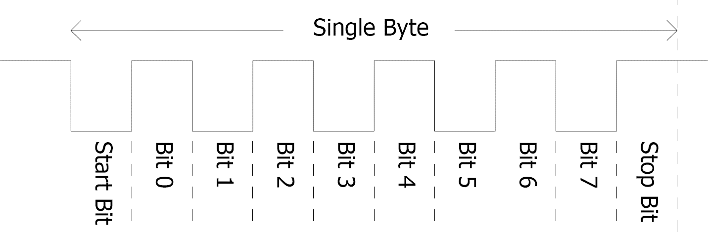
- Data format: 8 bits, No Parity, 1 Stop bit.
- Independent Baud rates from 300 baud up to 2M Baud (Refer to the Internal Functions Manual for details).
- Single byte transmits and receives a fully buffered service. The buffered service feature runs in the background capturing and buffering serial data without the user application having to constantly poll any of the serial ports. This frees up the application to service other tasks.

A single-byte serial transmission consists of the start bit, 8 bits of data followed by the stop bit. The start bit is always 0, while a stop bit is always 1. The LSB (Least Significant Bit, Bit 0) is sent out first following the start bit. The figure below shows a single-byte transmission timing diagram.
COM0 is also the primary interface for 4DGL user program downloads and chip configuration PmmC programming. Once the compiled 4DGL application program (EVE byte-code) is downloaded and the user code starts executing, the serial port is then available to the user application. Refer to the In-Circuit Serial Programming section for more details on PmmC/Firmware programming.
- TX0 pin (Serial Transmit COM0):
-
Dedicated Asynchronous Serial port COM0 transmit pin, TX0. Connect this pin to the external serial device receive (Rx) signal. This pin is 5.0V tolerant.
- RX0 pin (Serial Receive COM0):
-
Dedicated Asynchronous Serial port COM0 receive pin, RX0. Connect this pin to an external serial device transmit (Tx) signal. This pin is 5.0V tolerant.
- TX1 pin (Serial Transmit COM1):
-
Asynchronous Serial port COM1 transmit pin, TX1. Connect this pin to the external serial device receive (Rx) signal. This can be configured to one of the GPIO pins, see the table below.
- RX1 pin (Serial Receive COM1):
-
Asynchronous Serial port COM1 receive pin, RX1. Connect this pin to an external serial device transmit (Tx) signal. This can be configured to one of the GPIO pins, see the table below.
- TX2 pin (Serial Transmit COM2):
-
Asynchronous Serial port COM2 transmit pin, TX2. Connect this pin to the external serial device receive (Rx) signal. This can be configured to one of the GPIO pins, see the table below.
- RX2 pin (Serial Receive COM2):
-
Asynchronous Serial port COM2 receive pin, RX2. Connect this pin to an external serial device transmit (Tx) signal. This can be configured to one of the GPIO pins, see the table below.
- TX3 pin (Serial Transmit COM3):
-
Asynchronous Serial port COM3 transmit pin, TX3. Connect this pin to the external serial device receive (Rx) signal. This can be configured to one of the GPIO pins, see the table below.
- RX3 pin (Serial Receive COM3):
-
Asynchronous Serial port COM3 receive pin, RX3. Connect this pin to an external serial device transmit (Tx) signal. This can be configured to one of the GPIO pins, see the table below.
DIABLO-16 Serial TTL Comm Port Configuration Options
| TX1 | RX1 | TX2 | RX2 | TX3 | RX3 | |
|---|---|---|---|---|---|---|
| PA0 | Yes | Yes | Yes | |||
| PA1 | Yes | Yes | Yes | Yes | Yes | Yes |
| PA2 | Yes | Yes | Yes | |||
| PA3 | Yes | Yes | Yes | Yes | Yes | Yes |
| PA4 | Yes | Yes | Yes | Yes | Yes | Yes |
| PA5 | Yes | Yes | Yes | Yes | Yes | Yes |
| PA6 | Yes | Yes | Yes | Yes | Yes | Yes |
| PA7 | Yes | Yes | Yes | Yes | Yes | Yes |
| PA8 | Yes | Yes | Yes | Yes | Yes | Yes |
| PA9 | Yes | Yes | Yes | Yes | Yes | Yes |
| PA10 | Yes | Yes | Yes | |||
| PA11 | Yes | Yes | Yes | |||
| PA12 | Yes | Yes | Yes | Yes | Yes | Yes |
| PA13 | Yes | Yes | Yes | Yes | Yes | Yes |
| PA14 | ||||||
| PA15 |
Note
Pins PA0-PA3, PA14, PA15 are 3.3V tolerant only. Pins PA4-PA13 are 5.0V tolerant but have 3.3V output level.
Please refer to the DIABLO-16 Internal Functions Manual for information on how to set the DIABLO-16 pin mappings.
Audio Interface
The audio support in the DIABLO-16 Processor makes it better than its peers in the Graphics processor range. PWM ensures better sound quality with a volume range of 8 to 127. A simple instruction empowers the user to execute the audio files. The audio operation can be carried out simultaneously with the execution of other necessary instructions.
For a complete list of audio commands please refer to the DIABLO-16 4DGL Internal Functions manual.
- AUDIO pin (Audio PWM output):
-
External Amplifier Output pin. This pin provides a 16-bit DAC/PWM audio output to use with an external audio amplifier. If unused, then this pin must be left open or floating.
- AUDENB pin (Audio Enable output):
-
External Amplifier enable pin. This pin provides ON/OFF amplifier control. If unused, then this pin must be left open or floating.
-
LOW: Disable external Audio amplifier.
HIGH: Enable external Audio amplifier.
Touch Screen Interface
The DIABLO-16 supports 4-Wire resistive touch panels. The diagram below shows a simplified interface between the DIABLO-16 and a touch panel.

- XR pin (Touch Panel X-Read input):
-
4-Wire Resistive Touch Screen X-Read analog signal. Connect this pin to XR or X+ signal of the touch panel.
- XL pin (Touch Panel X-Drive output):
-
4-Wire Resistive Touch Screen X Drive signal. Connect this pin to XL or X- signal of the touch panel.
- YU pin (Touch Panel Y-Read input):
-
4-Wire Resistive Touch Screen Y-Read analog signal. Connect this pin to YU or Y+ signal of the touch panel.
- YD pin (Touch Panel Y-Drive output):
-
4-Wire Resistive Touch Screen Y Drive signal. Connect this pin to YD or Y- signal of the touch panel.
General Purpose I/O
There are 16 general-purpose Input/Output (GPIO) pins available to the user. These provide flexibility for individual bit operations along with serving collectively for byte-wise operations using the BUS functions
DIABLO-16 Alternate Pin Configurations GPIO
| Digital Input | Digital Output | Bus Read | Bus Write | Analog Read | |
|---|---|---|---|---|---|
| PA0 | Yes | Yes | Yes | Yes | Yes |
| PA1 | Yes | Yes | Yes | Yes | Yes |
| PA2 | Yes | Yes | Yes | Yes | Yes |
| PA3 | Yes | Yes | Yes | Yes | Yes |
| PA4 | Yes | Yes | Yes | Yes | |
| PA5 | Yes | Yes | Yes | Yes | |
| PA6 | Yes | Yes | Yes | Yes | |
| PA7 | Yes | Yes | Yes | Yes | |
| PA8 | Yes | Yes | Yes | Yes | |
| PA9 | Yes | Yes | Yes | Yes | |
| PA10 | Yes | Yes | Yes | Yes | |
| PA11 | Yes | Yes | Yes | Yes | |
| PA12 | Yes | Yes | Yes | Yes | |
| PA13 | Yes | Yes | Yes | Yes | |
| PA14 | Yes | Yes | Yes | ||
| PA15 | Yes | Yes | Yes |
Please refer to the DIABLO-16 Internal Functions Manual for information on how to set the DIABLO-16 pin mappings.
- PA0-PA3:
-
General purpose I/O pins, or can serve as Analog Input pins. Each pin can be individually set for INPUT or OUTPUT or ANALOG. Power-Up Reset default is all INPUTS. Digital GPIO can source/sink 10mA. These pins have a 0 to 3.3V range and have a 12-bit resolution. For more information, see the Specifications section.
-
When set as Analog Inputs, the pins have a 0 to 3.3V range and have a 12-bit resolution. For more information, refer to the Analog Inputs section.
- PA4-PA13:
-
General purpose I/O pins. Each pin can be individually set for INPUT or OUTPUT. Power-Up Reset default is all INPUTS. When set as Digital Inputs, the pins are 5V tolerant. Digital GPIO can source/sink 10mA. For more information, see the Specifications section.
- PA14-PA15:
-
General purpose I/O pins. Each pin can be individually set for INPUT or OUTPUT. Power-Up Reset default is all INPUTS. When set as Digital Inputs, the pins are 3.3V tolerant. Digital GPIO can source/sink 10mA. Under special situations, these pins can be used for a high-speed I2C interface. For more information, see the Specifications section.
System Pins
- VCC pins (Device Supply Voltage):
-
Device supply voltage pins. These pins must be connected to a regulated supply voltage in the range of 3.0 Volts to 3.6 Volts DC. The nominal operating voltage is 3.3 Volts.
- GND pins (Device Ground):
-
Device ground pins. These pins must be connected to the system ground.
- CLK1, CLK2 pins (Device Oscillator Inputs):
-
CLK1 and CLK2 are the device oscillator pins. Connect a 12MHz AT strip cut crystal with 22pF capacitors from each pin to GND as shown in the diagram below.

- AVCC pin (Analog Supply Voltage):
-
This is the analog supply voltage pin.
-
Option 1: This pin should be connected to VCC via a 12-ohm resistor, and also have a 4.7uF capacitor to AGND.
-
Option 2: Connect to VCC via an Inductor with a resistance of less than 1ohm and a capacity greater than 10mA, along with a 4.7uF Capacitor to AGND. This option provides the best ADC noise rejection.
This is NOT an analog reference.
AGND pin (Analog Ground):
This is the analog ground pin. This pin should be connected directly to GND
- RESET pin (Device Master Reset):
-
Device Master Reset pin. An active low pulse of greater than 2 microseconds will reset the device. Connect a resistor (1K to 10K, nominal 4.7K) from this pin to VCC. Only use open collector-type circuits to reset the device if an external reset is required. This pin is not driven low by any internal conditions.
Alternate Pin Functions
Most of the GPIO pins have an alternate function other than being for General Purpose I/O.
GPIO pins can be configured to be SPI, I2C, Serial or a range of other functions.
Note
Not all pins can be configured to be any of the alternate pin functions. Please refer to the tables.
Refer to the tables below that illustrate the GPIO pins you can associate with alternative functions.
DIABLO-16 Alternate Pin Configurations I/O Support Functions
| Pulse Out | PWM Out | Pin Counter | Quadrature In | |
|---|---|---|---|---|
| PA0 | Yes | Yes | ||
| PA1 | Yes | Yes | ||
| PA2 | Yes | Yes | ||
| PA3 | Yes | Yes | ||
| PA4 | Yes | Yes | Yes | Yes |
| PA5 | Yes | Yes | Yes | Yes |
| PA6 | Yes | Yes | Yes | Yes |
| PA7 | Yes | Yes | Yes | Yes |
| PA8 | Yes | Yes | Yes | Yes |
| PA9 | Yes | Yes | Yes | Yes |
| PA10 | Yes | |||
| PA11 | Yes | |||
| PA12 | Yes | |||
| PA13 | Yes | |||
| PA14 | ||||
| PA15 |
Note
- Once you allocate a pin to an alternate function, you can't allocate another pin to the same alternate function.
- Quadrature In requires 2 Pins
The table above illustrates the GPIO pins you can use for the 4 different I/O Support Functions.
Please refer to the DIABLO-16 Internal Functions Manual for more information on how to set the alternate pin configurations.
The Alternate pin functions have been broken up into a few tables for simplification. There are communication-based functions and I/O support-based functions.
Further information is available in the next sections for each of the alternative pin functions.
The table below illustrates the GPIO pins you can use for the three different SPI channels available.
DIABLO-16 Alternate Pin Configurations SPI Communications
| SPI1 SDO | SPI1 SDI | SPI1 SCK | SPI2 SDO | SPI2 SDI | SPI2 SCK | SPI3 SDO | SPI3 SDI | SPI3 SCK | |
|---|---|---|---|---|---|---|---|---|---|
| PA0 | Yes | Yes | Yes | ||||||
| PA1 | Yes | Yes | Yes | Yes | Yes | Yes | Yes | Yes | Yes |
| PA2 | Yes | Yes | Yes | ||||||
| PA3 | Yes | Yes | Yes | Yes | Yes | Yes | Yes | Yes | Yes |
| PA4 | Yes | Yes | Yes | Yes | Yes | Yes | Yes | Yes | |
| PA5 | Yes | Yes | Yes | Yes | Yes | Yes | Yes | Yes | |
| PA6 | Yes | Yes | Yes | Yes | Yes | Yes | Yes | Yes | |
| PA7 | Yes | Yes | Yes | Yes | Yes | Yes | Yes | Yes | |
| PA8 | Yes | Yes | Yes | Yes | Yes | Yes | Yes | Yes | |
| PA9 | Yes | Yes | Yes | Yes | Yes | Yes | Yes | Yes | |
| PA10 | Yes | Yes | Yes | ||||||
| PA11 | Yes | Yes | Yes | ||||||
| PA12 | Yes | Yes | Yes | Yes | Yes | Yes | Yes | Yes | |
| PA13 | Yes | Yes | Yes | Yes | Yes | Yes | Yes | Yes | |
| PA14 | |||||||||
| PA15 |
MOSI/MISO vs SDO/SDI naming conventions.
MOSI and MISO naming is used on many devices, where MOSI is MasterOutSlaveIn and MISO is MasterInSlaveOut.
SDI/SDO is also used on many devices and means SerialDataIn and SerialDataOut. Unlike MISO/MOSI conventions though, SDI/SDO is from the perspective of the device itself.
This table will hopefully bring clarity about how they connect.
| DIABLO-16 | Direction | Device |
|---|---|---|
| SDI (MISO) | <-- | SDO (MISO) |
| SDO (MOSI) | --> | SDI (MOSI) |
MOSI connects to MOSI, and MISO connects to MISO, however, SDI connects to SDO, and SDO connects to SDI. Take note so you connect your devices correctly.
The table below illustrates the GPIO pins you can use for the three different I2C channels available.
DIABLO-16 Alternate Pin Configurations I2C Communication
| I2C1 SDA | I2C1 SCL | I2C2 SDA | I2C2 SCL | I2C3 SDA | I2C3 SCL | |
|---|---|---|---|---|---|---|
| PA0 | Yes | Yes | Yes | Yes | Yes | Yes |
| PA1 | Yes | Yes | Yes | Yes | Yes | Yes |
| PA2 | Yes | Yes | Yes | Yes | Yes | Yes |
| PA3 | Yes | Yes | Yes | Yes | Yes | Yes |
| PA4 | Yes | Yes | Yes | Yes | Yes | Yes |
| PA5 | Yes | Yes | Yes | Yes | Yes | Yes |
| PA6 | Yes | Yes | Yes | Yes | Yes | Yes |
| PA7 | Yes | Yes | Yes | Yes | Yes | Yes |
| PA8 | Yes | Yes | Yes | Yes | Yes | Yes |
| PA9 | Yes | Yes | Yes | Yes | Yes | Yes |
| PA10 | Yes | Yes | Yes | Yes | Yes | Yes |
| PA11 | Yes | Yes | Yes | Yes | Yes | Yes |
| PA12 | Yes | Yes | Yes | Yes | Yes | Yes |
| PA13 | Yes | Yes | Yes | Yes | Yes | Yes |
| PA14 | SPECIAL | SPECIAL | SPECIAL | |||
| PA15 | SPECIAL | SPECIAL | SPECIAL |
Note
SPECIAL - please see I2C section.
SPI
There are 3 user-configurable SPI channels available for mapping to GPIO, for use by the user for the target application. All 3 SPI channels are Master only, and cannot be configured to be slaves at this time.
The SPI Bus speed is configurable using the SPIx_Init() Function in 4DGL and allows various speeds from 78.125Khz to 17.5Mhz.
Please refer to the table for details on which GPIO can be configured for SPI.
Note
The additional SPI channel (SPI0) is dedicated to the memory cards and cannot be reconfigured for alternate uses.
To map an SPI channel to a set of GPIO pins, the following 4DGL functions are used:
- SPIx_SCK_pin(pin); // Map the SCK pin
- SPIx_SDI_pin(pin); // Map the SDI pin
- SPIx_SDO_pin(pin); // Map the SDO pin
- where:
-
'SPIx' is substituted with SPI1, SPI2 or SPI3 accordingly, and
'pin' is the target GPIO pin compatible with that particular pin function.
Chip Select for use with SPI can be any other unused GPIO pin, configured as a Digital Output. The lowering and raising of the selected CS (GPIO) pin is done manually by the user in the 4DGL application.
Example Connection Diagram
This illustrates SPI being configured on GPIO PA4, PA6 and PA7, with user GPIO PA5 being used for the CS, and connections are to an external SPI Flash Chip.
Note
This example is an illustration of an SPI connection to the DIABLO-16 processor. It is not the complete circuit nor illustrates best practice.

Please refer to the DIABLO-16 Internal Functions Manual for more information on how to use the SPI functions.
I2C
There are 3 user-configurable I2C channels available for mapping to GPIO, for use by the user for the target application. All 3 I2C channels are Master only, and cannot be configured to be slaves at this time.
Please refer to the table for details on which GPIO can be configured for I2C.
To map an I2C Channel to a set of GPIO pins, the following 4DGL function is used:
- I2Cx_Open(Speed, SCLpin, SDApin);
- where:
-
'I2Cx' is substituted with I2C1, I2C2 or I2C3 accordingly,
'Speed' is the desired I2C Bus speed, and
'SCLpin' and 'SDApin' are the target GPIO pins compatible with that particular pin function.
Note
The normal I2C pins are PA0 to PA13, however, the use of these pins has a few limitations.
- There is no slew rate control at I2C_MED.
- I2C_FAST is not truly 1MHz.
If either of these restrictions needs to be addressed, a special case of SCLpin = PA14 and SDApin = PA15 exists ONLY for speeds I2C_MED (which uses slew rate control) and I2C_FAST (which is truly 1MHz)
Example Connection Diagram
This illustrates I2C being configured on GPIO PA8 and PA9, and connections are to an external I2C Analog Input ADC.
Note
This example is an illustration of an I2C connection to the DIABLO-16 processor. It is not the complete circuit nor illustrates best practice.

Please refer to the DIABLO-16 Internal Functions Manual for more information on how to use the I2C functions.
Pulse Out
Pulse Out is used to create a single pulse of set duration on the selected pin of choice, which is inverted in polarity to the current state of the pin.
This 'inversion of polarity' means if a Pin is currently held HI, and Pulse Out is executed on that Pin, the pin will pulse LO and then return to HI. Same with vice versa, if currently LO and Pulse Out are executed on that Pin, it will pulse HI and then return to LO.
This is available in both blocking and non-blocking versions.
Please refer to the table for details on which GPIO can be configured to Pulse Out.
Note
Each Pulse Out request needs at least a 1ms lead time due to the scheduling of the event with the internal 1ms timer.
To enable the Pulse Out function on a GPIO pin, the following 4DGL functions are used:
- pin_Pulseout(pin, value); //Non-Blocking
- pin_PulseoutB(pin, value); //Blocking
- where:
-
'pin' is the target GPIO pin compatible with that particular pin function, and
'value' is the length of the pulse in milliseconds.
Example Connection Diagram
This illustrates Pulse Out being configured on GPIO PA0 and is used to open an external relay via a transistor, for an application such as opening a door lock for a set duration.
Note
This example is an illustration of a PulseOut connection from the DIABLO-16 processor. It is not the complete circuit nor illustrates best practice.

Please refer to the DIABLO-16 Internal Functions Manual for more information on how to use the Pulse Out functions.
PWM Out
There are 6 PWM channels available to be configured by the user, with 4-time bases available for selection. The PWM can be configured to be used in Servo Mode, or Simple Mode.
Please refer to the table for details on which GPIO can be configured to PWM.
Servo Mode allows a millisecond input value with 0.01ms resolution, which runs at a frequency of approximately 50Hz or 50pps (20ms). The position of the servo is determined by the width of the pulse. Generally, 1.5ms is 90 degrees, 1ms is 0 degrees and 2ms is 180 degrees. Servos however vary, and the DIABLO-16 PWM control can be adjusted to suit most applications.
Simple Mode allows a percentage input value with a resolution of 0.1%, which runs at a frequency of approximately 70KHz.
To enable the PWM output on a GPIO pin, the following 4DGL function is used:
- PWM_Init(pin, mode, value);
- where:
-
'pin' is the GPIO compatible with the particular pin function,
'mode' is the type of PWM to generate, and
'value' is the parameter that defined the PWM pulse itself.
Example Connection Diagram
This illustrates PWM Out being configured on GPIO PA4 and is used to open an external relay via a transistor, for an application such as dimming a lamp.
Note
This example is an illustration of the PWM Out connection to the DIABLO-16 processor. It is not the complete circuit nor illustrates best practice.

Please refer to the DIABLO-16 Internal Functions Manual for more information on how to use the PWM functions.
Pin Counter
There are 6 Pin Counter channels available to be configured by the user, used to count incoming pulses with the ability to call a user function on overflow. The Pin Counter function is available for use in a variety of modes.
The counters can be read and written at any time.
Please refer to the table for details on which GPIO can be configured to Pin Counter.
To enable the Pin Counter function on a GPIO pin, the following 4DGL function is used:
- pin_Counter(pin, mode, OVFfunction);
- where:
-
'pin' is the GPIO pin compatible with this particular function,
'mode' is the type of trigger used to count on such as Rising/Falling/Edge, and
'OVFfunction' is the user function to call when the counter overflows if desired.
Example Connection Diagram
This illustrates the Pin Counter being configured on GPIO PA8 and is used to count pulses coming from a rotation sensor for example.
Note
This example is an illustration of a PIN Counter connection from the DIABLO-16 processor. It is not the complete circuit nor illustrates best practice.

Please refer to the DIABLO-16 Internal Functions Manual for more information on how to use the Pin Counter functions.
Quadrature In
There are two Quadrature Input channels available on the DIABLO-16 processor, which requires 2 GPIO pins each.
Please refer to the table for details on which GPIO can be configured for Quadrature Input.
Quadrature Input allows a quadrature encoder to be connected, and the position counter and delta counter can be read at any time.
To enable the Quadrature Input function on a set of GPIO pins (2 pins required), the following 4DGL function is used:
- Qencoderx(PHApin, PHBpin, mode);
- where:
-
'Qencoderx' is substituted for Quencoder1 or Quencoder2 accordingly,
'PHApin' is the pin connected to the A Phase of the Encoder,
'PHBpin' is the pin connected to the B Phase of the Encoder, and
'mode' is not currently used so is to be set to zero (0).
Example Connection Diagram
This illustrates Quadrature input being configured on GPIO PA2 and PA3 and is used to read pulses from a quadrature encoder.
Note
This example is an illustration of a quadrature input connection to the DIABLO-16 processor. It is not the complete circuit nor illustrates best practice.

Please refer to the DIABLO-16 Internal Functions Manual for more information on how to use the Quadrature Input functions.
Analog Inputs
Please refer to the table under the General Purpose I/O section for details about pins you can configure to analog inputs.
The analog inputs on the DIABLO-16 have a range of 0V to 3.3V, each with a max resolution of 12 bits. You can read the analog inputs using either the standard mode, averaged mode or high-speed mode.
- Standard Mode results are immediately read in a sample. Standard Mode can read over 40000 values per second. Operates at 12-bit.
- Averaged Mode results are immediately read in 16 samples and their average is returned. Averaged Mode can read ~20000 values per second. Operates at 12-bit.
- Highspeed Mode collects a user-specified number of samples at a user-specified rate/frequency and can execute a user function when complete. The updated value updates ~250000 times across 1-4 channels. Operates at 10-bit.
To enable a GPIO as an Analog Input for Standard or Averaged modes, you must use the following 4DGL function to set the pin:
Note
The various analog modes can interfere with the operation of the touch screen if their functions are called too frequently. It is recommended to limit the calls of the analog functions to a maximum of once every millisecond. Please refer to the Internal Functions documentation for further information on this topic. Not relevant if an external touch IC (or no touch) is used.
- pin_Set(mode, pin);
- where:
-
'mode' is the desired mode defined above, either Standard or Averaged, and
'pin' is the GPIO compatible with this function which is to become an Analog Input.
For highspeed mode, you must the following 4DGL function to set the pin and define the parameters:
- ana_HS(rate, samples, 1buf, 2buf, 3buf, 4buf, func);
- where:
-
'rate' is the number of samples per second,
'samples' is the number of samples to collect per channel,
'1buf' to '4buf' are the buffer addresses for the 4 channels, and
'func' is the user function to call when the number of samples specified has been collected.
Example Connection Diagram
This illustrates an analog input being configured on GPIO PA1 and is used to read an analog temperature from a temperature sensor.
Note
This example is an illustration of an analog input connected to the DIABLO-16 processor. It is not the complete circuit nor illustrates best practice.

Please refer to the DIABLO-16 Internal Functions Manual for more information on how to use the Analog Input functions.
DIABLO-16 Architecture
The figure below illustrates the DIABLO-16 Processor's architecture.

DIABLO-16 is a high-level graphics processor which runs the high-level 4DGL (4D Graphics Language).
It is not a conventional microcontroller with conventional microcontroller architecture, it is a custom graphics processor and therefore low-level access to the chip is not required nor available to the User.
4DGL provides high-level functions for the User and does all the low-level work in the background in a highly optimised fashion.
Flash Storage & RAM Allocation
The figure below illustrates how the FLASH and RAM are allocated in the System, and what is available for use by the system and by the user. Each area is explained in the sections following.

Loading of the PmmC, Display Driver and User Applications into their various places on the DIABLO-16 processor, is achieved using the Workshop4 IDE.
If a script for batch loading of the PmmC, Display Driver and/or User Applications without the use of Workshop4 is required, there is a script utility available.
Please refer to the Application Notes section of the 4D Labs website for information on this process.
PmmC / PmmC Loader
PmmC (Personality Module Micro-Code) - this is the operating system, incorporating the EVE runtime (Extensible Virtual Engine) which has an extensive byte-code instruction set programmed via the Workshop4 Software IDE.
The PmmC Loader can be thought of as a bootloader and allows the transfer of a PmmC from the User's PC into the System Flash storage on the DIABLO-16 processor.
Within the PmmC are over 450 built-in functions for graphics, sound, math functions etc, no need to include libraries, or wait for hefty compile times - it's all built-in.
The PmmC is in protected memory and cannot be read or damaged by inadvertent writes to illegal FLASH areas.
The PmmC may be upgraded at any time without disturbing any programs that may already exist in the 6 FLASH banks.
Display Driver
The DIABLO-16 is capable of interfacing with many different types of display devices. The DIABLO-16 has been designed for the maximum flexibility possible and therefore the Display Driver is modular and replaceable and separate from the PmmC.
The Display Driver may be upgraded at any time without disturbing any applications or data which may exist in the 6 FLASH banks, or the PmmC.
Loading the PmmC and/or Display Driver is achieved using our PmmC Loader tool or using the ScriptC command line tool.
Important
If you are wanting to use DIABLO-16 in a display, please contact the 4D Labs Tech Support or Sales departments, to discuss your requirements. Drivers can ONLY be created by 4D Labs, and depending on the display you have selected and the Driver IC it uses, will determine how difficult the process is. Please make contact with us BEFORE you start.
User Flash Memory Banks
The DIABLO-16 processor has 6 banks (Bank0 to Bank5) of Flash memory which can be used by the user to store application code or data, to be used by the display or stored for sending to an external device over comms. Each of the 6 banks is 32750 bytes in size, which provides over 12x the Flash capacity of the Picaso processor.
When a user's application is written to the Flash of the DIABLO-16 from the Workshop4 IDE Software, the user can choose the destination bank for the application to be stored in.
Bank0 is always the bank that is loaded on the start-up of the DIABLO-16. The bank0 application can then transfer control over to one of the other banks, and the application stored there will then run. This is achieved using the 4DGL flash_Run() function. Applications can freely change banks as required using this function, however a separate application (or Data) is required to reside in each bank, and a single application cannot take up more than 1 bank itself. When an application from another bank is run using the flash_Run() function, the processor is restarted and the execution from the other bank is started.
An application in one bank can store data in another bank using 4DGL commands such as:
- flash_Copy()
- flash_WriteBlock()
An application in one bank can store applications from a microSD card and write them to a bank for future execution using the 4DGL function flash_LoadFile().
An application in one bank can read data stored in another bank, such as graphics or strings stored there, retrieve them and display them as required. Reading of data from another bank is achieved using 4DGL functions such as:
- flash_GetByte()
- flash_GetWord()
- flash_putstr()
- flash_Blit2()
- flash_Blit4()
- flash_Blit8()
- flash_Blit16()
An application in a bank can erase other banks if required and can also erase itself which essentially formats the processor. Erasing of a bank is achieved in 4DGL using the flash_EraseBank() function.
Note
The flash_EraseBank() function should be used with caution as it will permanently erase any applications and/or data stored on that bank.
Please refer to the DIABLO-16 Internal Functions Manual for more information on how to read/write/erase/access and change between FLASH banks.
RAM (Both System and User)
The DIABLO-16 processor has two banks of RAM, one is 32KB of User RAM, and the other is a much smaller bank of System RAM which is only usable by the system, for its internal processes.
The System RAM is reserved for the system and is not accessible by the user. It is used for processes such as Audio Buffers, Intermediate File Buffers, Graphics Rendering, etc. This RAM ensures the user's RAM is not taken by the system.
No matter what options are enabled by the system, or by the user to influence the system (such as the size of the audio buffer), the system will never run out of RAM and try to encroach into the user's RAM space.
The DIABLO-16's 32768 (32KB) of User RAM is used to store variables and for user applications, sub-programs etc. Sub programs and Functions stored in RAM can be released when no longer required, freeing the memory for the user.
The user has full access to this 32KB of User RAM, and all internal processes of the DIABLO-16 use only the separate System RAM.
Programming Language
The DIABLO-16 processor belongs to a family of processors powered by a highly optimised softcore virtual engine called EVE (Extensible Virtual Engine). EVE was designed and created by 4D Systems in the early 2000s, and should not be confused with FTDI's solution of EVE, which was developed a decent decade or so later.
EVE is a proprietary, high-performance virtual machine with an extensive byte-code instruction set optimised to execute compiled 4DGL programs.
4DGL (4D Graphics Language) was specifically developed from the ground up for the EVE engine core. It is a high-level language that is easy to learn and simple to understand yet powerful enough to tackle many embedded graphics applications.
4DGL is a graphics-oriented language allowing rapid application development, and the syntax structure was designed using elements of popular languages such as C, Basic, Pascal and others.
Programmers familiar with these languages will feel right at home with 4DGL. It includes many familiar instructions such as IF..ELSE..ENDIF, WHILE..WEND, REPEAT..UNTIL, GOSUB..ENDSUB, GOTO, PRINT as well as some specialised instructions SERIN, SEROUT, GFX_LINE, GFX_CIRCLE and many more.
For detailed information about the 4DGL language, please refer to the following documents:
To assist with the development of 4DGL applications, the Workshop4 IDE combines a full-featured editor, a compiler, a linker and a downloader into a single PC-based application. It's all you need to code, test and run your applications.
4DGL is available to be written in two of the four environments offered by the Workshop4 IDE, Designer and ViSi. The other two environments, Serial and ViSi-Genie do not directly use 4DGL by the User (Except in Workshop4 Pro, for ViSi-Genie), however, it is present in the background. Serial is an application that runs, and that is written in 4DGL. ViSi-Genie automatically generates 4DGL itself based on what is configured in the GUI. More information about each follows.
In Circuit Serial Programming
The DIABLO-16 processor is a custom graphics processor. All functionality including the high-level commands is built into the chip. This chip-level configuration is available as a PmmC (Personality-module-micro-Code) file, which can be likened to traditional Firmware. There is also a Display Driver file, which separates specific display settings from the PmmC, unlike on the PICASO processor where everything is combined.
A PmmC file contains all of the low-level micro-code information (analogy of that of a soft silicon) which defines the characteristics and functionality of the device. The ability to program the device with a PmmC file provides an extremely flexible method of customising as well as upgrading it with future enhancements.
The Display Driver contains the initialisation and parameters associated with the particular display that is to be connected to the DIABLO-16 processor, along with product-specific settings and parameters which are required over and above what is found in the PmmC.
The PmmC file and Display Driver file can only be programmed into the device via the COM0 serial port and access to this must be provided on the target application board. This is referred to as In-Circuit Serial Programming (ICSP).
The PmmC file and Display Driver file are programmed into the device with the aid of Workshop4, the 4D Labs IDE software (See the Workshop4 IDE section). To provide a link between the PC and the ICSP interface, a specific 4D Programming Cable or Adaptor is required and is available from 4D Systems.
Using a non-4D programming interface could damage your processor, and void your warranty.
Note
The DIABLO-16 processor is shipped blank and it must be programmed with both the PmmC configuration and Display Driver files.
System Registers Memory Map
The following tables outline in detail the DIABLO-16 system registers and flags.
DIABLO-16 System Registers and Flags
| LABEL | ADDRESS DEC | ADDRESS HEX | USAGE |
|---|---|---|---|
| RANDOM_LO | 32 | 0x20 | random number generator LO word |
| RANDOM_HI | 33 | 0x21 | random number generator HI word |
| SYSTEM_TIMER_LO | 34 | 0x22 | 1msec 32 bit free running timer LO word |
| SYSTEM_TIMER_HI | 35 | 0x23 | 1msec 32 bit free running timer HI word |
| TIMER0 | 36 | 0x24 | 1msec user timer 0 |
| TIMER1 | 37 | 0x25 | 1msec user timer 1 |
| TIMER2 | 38 | 0x26 | 1msec user timer 2 |
| TIMER3 | 39 | 0x27 | 1msec user timer 3 |
| TIMER4 | 40 | 0x28 | 1msec user timer 4 |
| TIMER5 | 41 | 0x29 | 1msec user timer 5 |
| TIMER6 | 42 | 0x2A | 1msec user timer 6 |
| TIMER7 | 43 | 0x2B | 1msec user timer 7 |
| SYS_X_MAX | 44 | 0x2C | display hardware X res-1 |
| SYS_Y_MAX | 45 | 0x2D | display hardware Y res-1 |
| GFX_XMAX | 46 | 0x2E | current display width-1 determined by portrait / landscape swapping |
| GFX_YMAX | 47 | 0x2F | current display height-1 determined by portrait / landscape swapping |
| GFX_LEFT | 48 | 0x30 | virtual left point for most recent object |
| GFX_TOP | 49 | 0x31 | virtual top point for most recent object |
| GFX_RIGHT | 50 | 0x32 | virtual right point for most recent object |
| GFX_BOTTOM | 51 | 0x33 | virtual bottom point for most recent object |
| GFX_X1 | 52 | 0x34 | clipped left point for current object |
| GFX_Y1 | 53 | 0x35 | clipped top point for current object |
| GFX_X2 | 54 | 0x36 | clipped right point for current object |
| GFX_Y2 | 55 | 0x37 | clipped bottom point for current object |
| GFX_X_ORG | 56 | 0x38 | current X origin |
| GFX_Y_ORG | 57 | 0x39 | current Y origin |
| GFX_THUMB_PERCENT | 75 | 0x4B | size of slider thumb as percentage |
| GFX_THUMB_BORDER_DARK | 76 | 0x4C | darker shadow of thumb |
| GFX_THUMB_BORDER_LIGHT | 77 | 0x4D | lighter shadow of thumb |
| TOUCH_XMINCAL | 78 | 0x4E | touch calibration value |
| TOUCH_YMINCAL | 79 | 0x4F | touch calibration value |
| TOUCH_XMAXCAL | 80 | 0x50 | touch calibration value |
| TOUCH_YMAXCAL | 81 | 0x51 | touch calibration value |
| IMG_WIDTH | 82 | 0x52 | width of currently loaded image |
| IMG_HEIGHT | 83 | 0x53 | height of currently loaded image |
| IMG_FRAME_DELAY | 84 | 0x54 | if image, else inter frame delay for movie |
| IMG_FLAGS | 85 | 0x55 | bit 4 determines colour mode, other bits reserved |
| IMG_FRAME_COUNT | 86 | 0x56 | count of frames in a movie |
| IMG_PIXEL_COUNT_LO | 87 | 0x57 | count of pixels in the current frame |
| IMG_PIXEL_COUNT_HI | 88 | 0x58 | count of pixels in the current frame |
| IMG_CURRENT_FRAME | 89 | 0x59 | last frame shown |
| MEDIA_ADDRESS_LO | 90 | 0x5A | micro-SD byte address LO |
| MEDIA_ADDRESS_HI | 91 | 0x5B | micro-SD byte address HI |
| MEDIA_SECTOR_LO | 92 | 0x5C | micro-SD sector address LO |
| MEDIA_SECTOR_HI | 93 | 0x5D | micro-SD sector address HI |
| MEDIA_SECTOR_COUNT | 94 | 0x5E | micro-SD number of bytes remaining in sector |
| TEXT_XPOS | 95 | 0x5F | text curnt x pixel position |
| TEXT_YPOS | 96 | 0x60 | text current y pixel position |
| TEXT_MARGIN | 97 | 0x61 | text left pixel pos for carriage return |
| TXT_FONT_ID | 98 | 0x62 | font type, 0 = system font, else pointer to user font |
| TXT_FONT_MAX | 99 | 0x63 | max number of chars in font |
| TXT_FONT_OFFSET | 100 | 0x64 | starting offset (normally 0x20) |
| TXT_FONT_WIDTH | 101 | 0x65 | current font width |
| TXT_FONT_HEIGHT | 102 | 0x66 | current font height |
| GFX_TOUCH_REGION_X1 | 103 | 0x67 | touch capture region |
| GFX_TOUCH_REGION_Y1 | 104 | 0x68 | touch capture region |
| GFX_TOUCH_REGION_X2 | 105 | 0x69 | touch capture region |
| GFX_TOUCH_REGION_Y2 | 106 | 0x6A | touch capture region) |
| GFX_CLIP_LEFT_VAL | 107 | 0x6B | left clipping point (set with gfx_ClipWindow(...) |
| GFX_CLIP_TOP_VAL | 108 | 0x6C | top clipping point (set with gfx_ClipWindow(...) |
| GFX_CLIP_RIGHT_VAL | 109 | 0x6D | right clipping point (set with gfx_ClipWindow(...) |
| GFX_CLIP_BOTTOM_VAL | 110 | 0x6E | bottom clipping point (set with gfx_ClipWindow(...) |
| GFX_CLIP_LEFT | 111 | 0x6F | current clip value (reads full size if clipping turned off) |
| GFX_CLIP_TOP | 112 | 0x70 | current clip value (reads full size if clipping turned off) |
| GFX_CLIP_RIGHT | 113 | 0x71 | current clip value (reads full size if clipping turned off) |
| GFX_CLIP_BOTTOM | 114 | 0x72 | current clip value (reads full size if clipping turned off) |
| GRAM_PIXEL_COUNT_LO | 115 | 0x73 | LO word of count of pixels in the set GRAM area |
| GRAM_PIXEL_COUNT_HI | 116 | 0x74 | HI word of count of pixels in the set GRAM area |
| TOUCH_RAW_X | 117 | 0x75 | 12 bit raw A2D X value from touch screen |
| TOUCH_RAW_Y | 118 | 0x76 | 12 bit raw A2D Y value from touch screen |
| GFX_LAST_CHAR_WIDTH | 119 | 0x77 | calculated char width from last call to charWidth function |
| GFX_LAST_CHAR_HEIGHT | 120 | 0x78 | calculated height from last call to charHeight function |
| GFX_LAST_STR_HEIGHT | 121 | 0x79 | calculated width from last call to strWidth function |
| GFX_LAST_CHAR_WIDTH | 122 | 0x7A | calculated height from last call to strHeight function |
| PIN_COUNTER_PA4 | 123 | 0x7B | pin counter for PA4 |
| PIN_COUNTER_PA5 | 124 | 0x7C | pin counter for PA5 |
| PIN_COUNTER_PA6 | 125 | 0x7D | pin counter for PA6 |
| PIN_COUNTER_PA7 | 126 | 0x7E | pin counter for PA7 |
| PIN_COUNTER_PA8 | 127 | 0x7F | pin counter for PA8 |
| PIN_COUNTER_PA9 | 128 | 0x80 | pin counter for PA9 |
| PIN_EVENT_PA4 | 129 | 0x81 | pin counter rollover event for PA4 |
| PIN_EVENT_PA5 | 130 | 0x82 | pin counter rollover event for PA5 |
| PIN_EVENT_PA6 | 131 | 0x83 | pin counter rollover event for PA6 |
| PIN_EVENT_PA7 | 132 | 0x84 | pin counter rollover event for PA7 |
| PIN_EVENT_PA8 | 133 | 0x85 | pin counter rollover event for PA8 |
| PIN_EVENT_PA9 | 134 | 0x86 | pin counter rollover event for PA9 |
| QEN1_COUNTER_LO | 135 | 0x87 | quadrature encoder #1 counter LO |
| QEN1_COUNTER_HI | 136 | 0x88 | quadrature encoder #1 counter HI |
| QEN1_DELTA | 137 | 0x89 | quadrature encoder #1 delta count |
| QEN2_COUNTER_LO | 138 | 0x8A | quadrature encoder #2 counter LO |
| QEN2_COUNTER_HI | 139 | 0x8B | quadrature encoder #2 counter HI |
| QEN2_DELTA | 140 | 0x8C | quadrature encoder #2 delta count |
| FALSE_REASON | 141 | 0x8D | explanation 'false' results, currently only for flash_functions |
Note
These registers are accessible with peekW and pokeW functions.
Memory Cards - FAT16

The DIABLO-16 Processor uses off-the-shelf standard SDHC/SD/micro-SD memory cards with up to 4GB capacity usable with FAT16 formatting. For any FAT file-related operations, before the memory card can be used it must first be formatted with the FAT16 option. The formatting of the card can be done on any PC system with a card reader. Select the appropriate drive and choose the FAT16 (or just FAT in some systems) option when formatting. The card is now ready to be used in the DIABLO-16 based application.
 DIABLO-16 Processor also supports high-capacity HC memory cards (4GB and above). The available capacity of SD-HC cards varies according to the way the card is partitioned and the commands used to access it.
The FAT partition is always first (if it exists) and can be up to the maximum size permitted by FAT16. Windows 7 will format FAT16 up to 4GB. Windows XP will format FAT16 up to 2GB and the Windows XP command prompt will format FAT16 up to 4GB.
RMPET, a 4D Labs tool found in the Workshop4 IDE, is capable of repartitioning and formatting microSD cards to be the appropriate type and format. This should be used for all cards.
Note
An SPI Compatible SDHC/SD/micro-SD card MUST be used. DIABLO-16 along with other 4D Labs Processors require SPI mode to communicate with the SD card. If a non-SPI compatible SD card is used then the processor will simply not be able to mount the card.
Hardware Tools
The following hardware tools are required for full control of the DIABLO-16 Processor.
4D Programming Adaptors
The 4D Programming Cable, uUSB-PA5-II and 4D-UPA are essential hardware tools to program, customise and test the DIABLO-16 Processor.
Note
Any of the 4D Programming Cable, uUSB-PA5-II or 4D-UPA can be used, along with previous generation 4D programmers too.
The 4D programming interfaces are used to program a new Firmware/PmmC, Display Driver and for downloading compiled 4DGL code into the processor. They even serve as an interface for communicating serial data to the PC.
The 4D Programming Cable, uUSB-PA5 and gen4-PA Programming Adaptor are available from the 4D Systems website.
Using a non-4D programming interface could damage your processor, and void your warranty.


Evaluation Display Modules
4D Systems has several modules available which can be used for evaluation purposes or equally as final products, to discover what the DIABLO-16 processor has to offer.

gen4-uLCD-70DT - 7.0" Resistive Touch DIABLO-16 Intelligent Display Module

gen4-uLCD-43DT - 4.3" Resistive Touch DIABLO-16 Intelligent Display Module

gen4-uLCD-35DT - 3.5" Resistive Touch DIABLO-16 Intelligent Display Module
Other modules are also available. Please contact 4D Systems for more information, or visit the 4D Systems website.
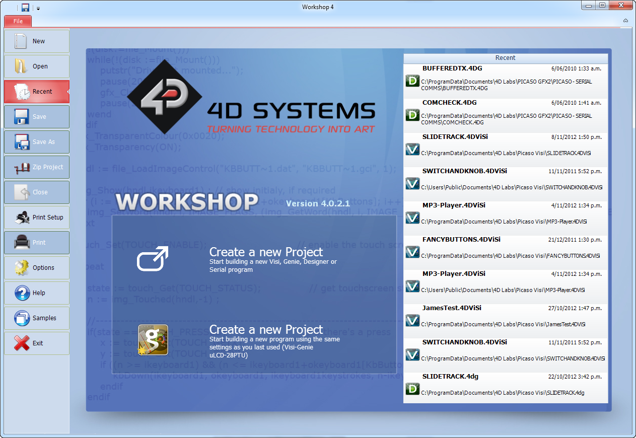
Workshop4 IDE
Workshop4 is a comprehensive software IDE that provides an integrated software development platform for all of the 4D family of processors and modules. The IDE combines the Editor, Compiler, Linker and Downloader to develop complete 4DGL application code. All user application code is developed within the Workshop4 IDE.
The Workshop4 IDE supports multiple development environments for the user, to cater to different user requirements and skill levels.
- The Designer environment enables the user to write 4DGL code in its natural form to program the range of 4D System's intelligent displays.
- A visual programming experience, suitably called ViSi, enables drag-and-drop type placement of objects to assist with 4DGL code generation and allows the user to visualise how the display will look while being developed.
- An advanced environment called ViSi-Genie doesn't require any 4DGL coding at all, it is all done automatically for you. Simply lay the display out with the objects you want, set the events to drive them and the code is written for you automatically. This can be extended with additional features when a Workshop4 PRO license is purchased from the 4D Systems website. Extended Advanced features for Visi-Genie are available in the PRO version of WS4. Further details are explained in the Visi Genie section of the Workshop4 documentation.
- A Serial environment is also provided to transform the display module into a slave serial module, allowing the user to control the display from any host microcontroller or device with a serial port.
For more information regarding these environments, refer to the Workshop4 manuals.
The Workshop4 IDE is available from the 4D Systems website.
Reference Design

Package Details

PCB Land Pattern

Specifications
Absolute Maximum Ratings
| Operating ambient temperature | -40°C to +85°C |
| Storage temperature | -65°C +150°C |
| Voltage on VCC with respect to GND | -0.3V to 4.0V |
| Maximum current out of GND pin | 320mA |
| Maximum current into VCC pin | 320mA |
| Maximum current sunk/sourced by any pin | 10.0mA |
| Maximum current sunk/sourced by all ports | 200.0mA |
| Total power dissipation | 1.0W + I/O Load |
Note
Stresses above those listed here may cause permanent damage to the device. This is a stress rating only and functional operation of the device at those or any other conditions above those indicated in the recommended operation listings of this specification is not implied. Exposure to maximum rating conditions for extended periods may affect device reliability.
Recommended Operating Conditions
| Parameter | Conditions | Min | Typ | Max | Units |
|---|---|---|---|---|---|
| Supply Voltage (VCC) | 3.0 | 3.3 | 3.6 | V | |
| Operating Temperature | 40 | -- | +85 | °C | |
| External Crystal (Xtal) | -- | 12.00 | -- | MHz | |
| Input Low Voltage (VIL) | VCC = 3.3V, all pins | VGND | -- | 0.2VCC | V |
| Input High Voltage (VIH) | VCC = 3.3V, non 5V tolerant pins | 0.8VCC | -- | VCC | V |
| Input High Voltage (VIH) | PA4-PA13 GPIO, RX0 and TX0 pins | 0.8VCC | -- | 5.5 | V |
Global Characteristics Based on Operating Conditions
| Parameter | Conditions | Min | Typ | Max | Units |
|---|---|---|---|---|---|
| Supply Current (ICC) | VCC = 3.3V | -- | 70 | -- | mA |
| Internal Operating Frequency | Xtal = 12.00MHz | -- | 70.00 | -- | MHz |
| Output Low Voltage (VOL) | VCC = 3.3V, IOL <= 10mA | -- | -- | 0.4 | V |
| Output High Voltage (VOH) | VCC = 3.3V, IOL >= -10.0mA | 2.4 | -- | -- | V |
| Capacitive Loading | CLK1, CLK2 pins | -- | -- | 15 | pF |
| Capacitive Loading | All other pins | -- | -- | 50 | pF |
| Flash Memory Endurance | Programming | -- | 10000 | -- | E/W |
Analog To Digital Module Specification
| Parameter | Conditions | Min | Typ | Max | Units |
|---|---|---|---|---|---|
| A/D Converter Resolution | PA0-PA3(pin_Read) XR, YU pins (Resistive Touch) |
-- | -- | 12 | bits |
| PA0-PA3(ana_HS) | -- | -- | 10 | bits | |
| A/D Integral Nonlinearity | PA0-PA3(pin_Read) | -2 | -- | +2 | LSb |
| PA0-PA3(ana_HS) | -1.5 | -- | +1.5 | LSb | |
| A/D Differential Nonlinearity | PA0-PA3 | >-1 | -- | <1 | LSb |
| A/D Gain Error | PA0-PA3(pin_Read) | 2 | 3 | 7 | LSb |
| PA0-PA3(ana_HS) | 1 | 5 | 6 | LSb | |
| A/D Offset Error | PA0-PA3(pin_Read) | 2 | 3 | 5 | LSb |
| PA0-PA3(ana_HS) | 1 | 2 | 5 | LSb | |
| A/D THD | PA0-PA3(pin_Read) | -- | -- | -75 | dB |
| PA0-PA3(ana_HS) | -- | -- | -64 | dB | |
| A/D Signal to Noise + Distortion | PA0-PA3(pin_Read) | 68.5 | 69.5 | -- | dB |
| PA0-PA3(ana_HS) | 57 | 58.5 | -64 | dB | |
| A/D Spurious Free Dynamic Range | PA0-PA3(pin_Read) | 80 | -- | -- | dB |
| PA0-PA3(ana_HS) | 72 | -- | -- | dB | |
| A/D Effective Resolution Bits | PA0-PA3(pin_Read) | 11.09 | 11.3 | -- | Bits |
| PA0-PA3(ana_HS) | 9.16 | 9.4 | -- | Bits |
Ordering Information
| Order Code: DIABLO-16 |
| Package: TQFP-64, 10mm x 10mm |
| Packaging: Trays of 160 pieces |
Revision History
| Revision Number | Date | Description |
|---|---|---|
| 1.6 | 05/10/2015 | Corrected issues with GPIO descriptions and voltage tolerances in the Pinout table. Corrected issues with voltage tolerances in Specifications table. Updated Evaluation Module listing. Updated Reference Schematic. |
| 1.7 | 06/10/2015 | Corrected detail about PA14/PA15 – these are capable of being GPIO, not just Input Only. |
| 1.8 | 12/08/2016 | Added detail to the Display Driver section |
| 2.0 | 01/05/2017 | Updated formatting and contents |
| 2.1 | 21/03/2019 | Updated formatting and minor content changes |
| 2.2 | 11/11/2019 | Corrected issues with voltage tolerance in Serial Ports – voltage tolerance depends on GPIO pin used. |
| 2.3 | 08/03/2021 | Added detail for A/D module specifications |
| 2.4 | 22/09/2021 | Fixed incorrect note about 600K max baud, should be 2M baud |
| 2.5 | 27/09/2021 | Added MOSI/MISO vs SDO/SDI explanation and table in the Alternate Pin Functions |
| 2.6 | 13/12/2021 | Fixed typo's of Kb or kb, to be the correct KB (Kilobyte) case |
| 2.7 | 27/02/2023 | Modified datasheet for web-based documentation. |
| 2.8 | 28/11/2023 | Added pin 35 as VCC in pin table summary |